Tuesday, May 11, 2021

Know More about Drag Conveyors Right Here

In special transportation of smaller capacities dragging chain conveyors are used. The working of Drag chain conveyors is based on the principle of a chain-and-flight combination pulling a volume of material along. With different flights/paddles, the chain is equipped and points to several discharging points it drags the material from various charging.


Mainly for dusty, abrasive, or hot material, the enclosed conveying device is used and in coal, it has a very limited application. However, specialized conveying systems are needed by the power plant industry and other coal industry players, for which the very flexible drag chain conveyor, might be the only solution. There are many dragging chain supplier who provides good quality products.

To safely move large volumes of product material, handling equipment is used and it performs it with great efficiency. The conveyor is the most common form of this technology that transports material from its inlet to its discharge end via buckets, chains, augers, belts, and more uses mechanized movement. You can understand conveyor systems by visiting different articles as in this article we will learn basics about the drag conveyor. This conveyor class, which is otherwise known as paddle, drag chain, scraper, or en masse conveyors, is a continuous device. It can accelerate bulk products with ease and perform quick aggregates and other materials working. These are quite reliable.

In terms of operation, drag conveyors are not unlike most other conveyors. It is a motor power with an endless single or double-stranded chain of flights which through the bottom of the conveyor pulls or drags material. The chain can be completely enclosed or partially, but in maximum cases, to allow material to be dragged by the flights to the outlet there must be some form of housing.


For dry, free-flowing materials drag conveyors are very well suited and for cement, railway, chemical, agricultural, and other applications these are most useful which need metering and efficient movement of product. They can be horizontal or inclined, but for vertical conveying, their paddles must be designed by a dragging chain manufacturer.

You can find a reliable manufacturing team online that can give you the best deal.


Wednesday, April 7, 2021

Tips to Achieve Gear Coupling Reliability

For connecting process equipment gear coupling is among the most commonly used methods. They can provide long life and good reliability when properly selected, installed, and maintained.

Over other couplings, Gear Coupling offers several advantages, including very high torque density, moderate misalignment capacity, and exceptional tensional stiffness and.


However, you will find many areas where failures may be initiated when it comes to gear coupling reliability. Because of a lack of knowledge or a lack of execution of certain fundamentals generally, these failures begin, which are very much important for these couplings to run reliably.

Installation

Due to their installation few couplings don’t get much of a chance at a decent life. There are times these parts don’t die but are murdered just like other components that experience infant mortality. If optimum reliability is to be obtained then certain elements of gear coupling installation must be considered by gear coupling manufacturer, including:

Keys and Keyway Fits - To reduce the risk for fatigue cracking keyways should have a proper radius. To minimize the coupling imbalance key lengths should be measured.

Hub and Sleeve Fit – You need to determine the type of hub fit. To offset centrifugal force effects on shaft/hub contact pressures higher speed applications should have an adequate interference fit. Excessive hub interference fits can result in hub cracks and hub failure.

Fastener Assembly – Select the correct type of fasteners and the proper arrangement. They may put the threads in the shear plane so that standard bolts can work. Coupling bolts require correct preload, which can only be achieved by proper bolt torque methods.

Correct Coupling Gaps -The shafts may impact one another under misalignment if floating shafts have a small coupling gap.


Proper Sealing – You need to use proper gaskets and O-rings so the lubricant stays in the coupling.

Hub Installation - If you want that your hub material properties are not compromised then you need to choose proper heating methods from gear coupling supplier and for interference fit hubs you need to select the proper heating magnitude.

Lubrication - For optimum gear coupling reliability get the right product in the right amount at the right time.


Tuesday, February 16, 2021

The Function and Usage of Gearboxes

From a rotating power source to another device using gear ratios, a gearbox provides torque and speed conversions. It can be used in various situations such as pedal bicycles, fixed machines, and anywhere else rotational torque and speed need to be adapted. But, in motor vehicles, the most commonplace is where the drive wheels, the gearbox with taper bush adapts the output of the internal combustion engine. They cannot be used in many operations such as stopping or starting as these engines need to be operated at a relatively high rotational speed.


They must be largely used in cars as gearboxes are so widely used in motor vehicles. More and more cars are consumed with the development of our economy as a result, gearboxes are playing a more crucial role in our daily life. Few of them have the knowledge of how a car works although many people have cars, let alone the relationship between various mechanical components. For car owners, It is a wise decision to learn something about gearboxes from taper bush suppliers as car gearboxes are the basic parts for its working process.

To the crankshaft of the engine, the gearbox will generally be connected in cars. And driving the wheels, the output of the transmission via the drive shaft is transmitted to various differentials. Pushing the car forward, the gearbox converts engine speed into torque. It is the major job of the gearbox. Between automatic cars and manual cars, there is some difference.


Used in many other places except in cars, there is no doubt that gearboxes from taper bush manufacturer. But no matter where they are used i.e. the gear ratio cannot be changed during the usage, these transmissions share an important feature. It is because at the time the transmission is set, the gear ratio is fixed.

All in all, there is more knowledge about their functions and gearboxes. Of gearboxes, you should have some basic knowledge. In your future life, maybe it will be helpful.


Uses and Types of Gears According to Axle or Shaft Position

Depending on its purpose, there are several different kinds of gears manufactured according to sizes, shafts, material, and so on, all designed available in the market. According to the arrangement of the axle or PTO shaft, used to classify each type of gear, there are different criteria a popular method is categorizing them. 3 kinds of shaft arrangement are there, namely parallel shafts, non-parallel axis, and non-intersecting or intersecting shafts.


First, at the same surface level, parallel shaft gears are the type of gears that interlock. To transfer the power of rotational motion between the parallel shafts, they function as a mechanism. Designed for long-term efficiency, the advantages are these gears provide maximum horsepower. Also when it operates, it does not make much noise and can carry a high load. Production of these types of gear On the other hand creates axial thrust and is expensive. With manual transmissions like car steering and clock, these gears are used for machines generally.

Second, to allow smooth transfer of motion and power between axes that are angled to be perpendicular with each other, intersecting shaft gears from PTO shaft suppliers are designed. Falling into this category, the following are types of gears: crown gear, coniflex, bevel, and angular. Requiring strength and speed, their purpose is to power machines that because it can handle high load capacity. Intersecting gears are more inexpensive as compared to the parallel shaft. These types of gears are typically used to power marine applications, locomotives, hand drills, and much more.


Lastly, while using gears with non-intersecting axes, used on applications, non-parallel or non-intersecting shaft gears are that require high-ratio speed reduction providing power transmission within a limited area. Because its production cost is also the lowest, it has a limited load capability although it is the most inexpensive type of gear from a PTO shaft manufacturer. By lowering the ratios to increase efficiency, this setback can be solved easily.

Categorizing the use of gears, this is only one of many systems. Gears are categorized according to materials pitch diameter used to manufacturing precision, manufacture the gear, number of housing design and steps among others.


Tuesday, November 24, 2020

Learn How to Achieve Gear Coupling Reliability

For connecting process equipment gear couplings are among the most commonly used methods. They can provide long life and good reliability if properly selected, installed, and maintained.


Compared to other couplings, gear couplings offer several benefits, including very high torque density, moderate misalignment capacity, and exceptional torsional stiffness.

However, when the question arises regarding gear coupling reliability, you will find many areas where failures may be initiated. Due to the lack of knowledge or execution of certain basics, these failures begin. These are necessary for these gear coupling to run reliably.

Design, Selection, and Sizing

For gear coupling reliability selecting the correct coupling for the application is critical. 

Select the coupling style and design.

From the original equipment manufacturer’s (OEM) gear coupling charts you need to select the service factor (SF). If adequate SF is not used, shock loads or variable loading can cause premature failure. For gear coupling sizing some gear coupling manufacturers may even specify a misalignment factor when higher coupling misalignment is expected.

Based on the design of brake horsepower (BHP), SF, and speed you should calculate application torque (T) requirements.

You should select a coupling with a torque capacity greater than the torque requirements. There is no reason to add additional capacity because the service factor is already factored in.

Compared to the actual application bore, you need to confirm that the coupling selected has a greater bore capacity. Frequently the maximum bore size will even increase the coupling torque capacity two to three times what was previously calculated and drive the coupling sizing process.


You need to verify the shaft depth available for the coupling hub and compare it with the actual hub depth. In case the hub is too long, it must be either overhung or machined off. You will find some good gear coupling suppliers according to your type.

Make sure that the coupling will fit around the equipment and guard. When there is a design modification on existing equipment this is typically something that can become an issue. In the long run, guards that allow maintainability will encourage proper maintenance.


Tuesday, October 6, 2020

Know about the Drag Chain

The conveyor consists of a sequence being drawn through a pipe. Units handling several tons per hour are often constructed using basic workshop facilities.


The operation was demonstrated with a typical mineral and typical grains, employing a chain with 25-mm links in pipes with diameters of 25, 38, or 50 mm. Angles ranged from horizontal to 60° and chain speeds from 0.2 to 4 m/s. Through-put varied linearly with chain speed from dragging chain supplier so that the device has potential also as a controlled solids feeder. The correlations presented enable the essential design parameters of the conveyor to be estimated for materials resembling those tested.

The conveyor is meant for little through-puts over distances within 100 m, and when power consumption isn't a clincher. The speed of wear and tear will depend upon the character of the feed. The suitability of the conveyor for any specific application has got to be determined experimentally.

Chain/Tow/Drag Line Conveyor

The dragging chain uses mechanical devices attached to moving members, usually chains or cables, to tug or to products. Drag conveyors are used for moving bulk materials in bins, flights, or other attachments and may have multiple discharge or loading points. Tubular drag conveyors use an enclosed system of chains to convey products in any direction. Chain conveyors use a sequence, or multiple chains to maneuver pallets or other hard-to-convey products. Tow conveyors use a towline like cables or chains, usually within the floor or simply above it, to tow products directly or to tow wheeled carts or dollies.

Drag chain conveyors are used for special transportation of smaller capacities. Drag chain conveyors work on the principle of a chain-and-flight combination pulling a volume of fabric along. The chain is provided with different flights/paddles and drags the fabric from various charging points to a variety of discharge points.


The enclosed conveying device is employed mainly for dusty, abrasive, or hot material and, as such, has only a really limited application in coal. However, the facility plant industry and other industry players invite specialized conveying systems, that the very flexible drag chain conveyor from dragging chain manufacturer could be an answer.

Horizontal, vertical, or inclined solutions, with a possible explosion-proof and dust-tight design, could be necessary for a few special applications within the industry.


Thursday, July 16, 2020

Know Everything about Gear Couplings

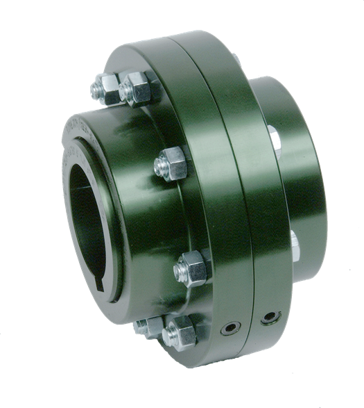
In mechanical power transmission gear coupling is a popular form of flexible coupling. What has made them one of the most preferred types of mechanical power transmission couplings is their suitability to a wide application like usability, areas & easiness in installation. Basically, between two connected shafts, they form a mechanical device that has a high capacity of transmitting 'torque', which is not collinear.


In performance they are considered as torsional rigid, their basic design can be divided into two major types:

Two external gear hubs are present in a fully flexible type coupling usually with finished bore & keyway mounted on connecting shafts. With internal teeth of common teeth are engaged in these hubs, which form a spline-like joint for power transmission.

2 halves, rigid and flexible are therein a semi-flexible coupling primarily. One end rigidity does not accommodate the parallel displacement of shafts but since it has flexible members; it surely does accommodate angular misalignment. This type of coupling is primarily employed in floating shaft applications.

In finished bore usually, a gear coupling from gear coupling supplier is supplied & installed & keyway conditions with specified dimensions against the requirement of the application.

What makes them suitable for a wide range of mechanical power transmission applications is the flexibility to absorb misalignment between 2 shafts, torsional rigidity, ease in installation & maintenance & most importantly high torque transmission capacity at low vibrations.

In design gear, teeth of the coupling is crowned which gives you the scope for absorbing angular misalignment while the scope for adjusting the linear misalignment is provided by the backlash between the mating teeth, which in turn makes the join, vibration-free during rotation.

Seals, machines, bearings, and shafts are therefore not subjected to the additional forces as large axial moments are avoided, sometimes of considerable magnitude.


There is extensive use of the gear couplings from gear coupling manufacturer in majority application areas such as heavy gearboxes, transmission drives, engines, fluid couplings similar where high torque transmission capacity along with torsional rigidity is required.

Follow our Facebook and Twitter for more information about our product.


How to Choose the Right Conveyor Chain for Your Application

For the maximum performance of a conveyor chain, four critical criteria are required. They are wearing ability, impact resistance, and ultimate strength and fatigue resistance.

The measurement that determines the ultimate strength of the conveyor chain is the weight in pounds required to break the chain on a linear plane. By using a tensile testing machine the usual method of testing is done. ANSI dictates the minimum strength values for each size of the chain.


The material by which the chain is made, its hardening specifications, and its manufacturing process that is used in making its components consist of a pin, center link, and side link is controlled by the manufacturer and determines the strength of the chain.

While comparing chains a conveyor chain's durability value is the most subjective value to consider. Its durability is affected by factors such as chain speed, lubrication, loads, and system design among others. Only the hardness factor is controlled by a manufacturer that impacts the other three criteria.

It is a fact that the durability the factor of a chain from conveyor chain manufacturer depends on how hard the chain is but along with this comes to lower resistance to fatigue and impact. The more the chain is harder the less resistance it becomes to fatigue and impact.


While the chain is moving around its horizontal turns, the side loads between the chain and the rollers or traction wheel make for a subtle bending motion in the center link of the conveyor chain. For fatigue, this particular movement is the catalyst. The fatigue should not go unnoticed and therefore, hence the chain is not replaced at once and the instance of failure is diminished.

In the case of loads that are often stopped and started, the chain particularly the pusher dog is subject to impact failure if an impact-resistant material was not used in its manufacture. The loading and unloading sites are other possible points of impact on a conveyor from the conveyor chain supplier. Impact failures happen with no warning like fatigue failures, but they do not, as a rule, spread out as the fatigue failures do.


Thing to Learn About Bevel Gears

The  bevel gear  has a conical form and through shafts that are typically at an angle of 90 degrees to each other, these can be used to tran...